TT250 Electrical System Tutorial
The TT250 electrical system is simple, easy to understand, and easy to maintain. This maintenance tutorial explains the system’s main components, their locations, their functions, and some suggestions in the unlikely event you’ll ever need to troubleshoot the system.
The TT250 has an 18-pole, 300-watt stator that puts out plenty of power. Many riders like to run accessories (heated vests, spotlights, heated grips, etc.), and on bikes with smaller electrical outputs, you can run the battery down while riding with all the accessories powered up. The TT250 won’t have this problem. It’s got the juice you need.
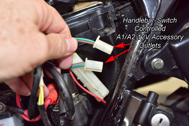
A cool feature on the TT250 is the built-in accessory outlets already wired into the main harness, and the accessories switch located on the right handlebar. On the non-US bikes, that switch was used for the headlights and parking lights. In the US, the headlights have to be on all the time, so the switch isn’t necessary. We didn’t want to give up the switch, though, so we’re using it to control the underseat accessories outlets.
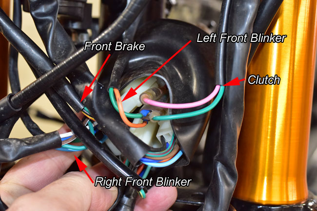
Let’s get on to the main attraction, and that’s the CSC TT250 electrical system and its components. Most of the electrical and electronic components on this bike are located under the seat and tank, and behind the headlight.
You can decide best which components you’ll need to remove based on which components you want to access. In this tutorial, we’ve removed the seat, the fuel tank, and the headlight so you can see everything. The first part of our tutorial below focuses on removing these items; the second part identifies various electronic component locations.
Body Panel, Seat, Fuel Tank, and Headlight Removal
Remove the rear body panels on the left and right side of the motorcycle. There’s a single bolt in each one. They pop off after you have removed the bolt.
Removing the tank involves:
These actions are shown in the photos below.
The first component is the ignition switch, located on top of the forks.
As you can see from the photo above, red is positive, and green is ground. Throughout the motorcycle, wires with green insulation are ground wires.
The regulator/rectifier is on the left side of the motorcycle near the front of the bike. It mounts to the frame beneath the fuel tank. If this component is not working, the battery will not charge properly or it may overcharge and boil over. The red and green wires go to the battery to charge it. The yellow wires come from the motorcycle’s stator.
If the motorcycle loses all electrical power, there are several potential causes, but the most likely are that this fuse has opened, or the engine kill switch is in the off position. Don’t laugh about that last one. We regularly get calls in which the caller tells us the bike has lost all electrical power. In those cases, it’s almost always because the owner inadvertently has the kill switch in the off position. I’ve done it, too. I’m just mentioning it here because it’s the first thing I would check having answered a few of those calls, and because I’ve made that mistake myself (i.e., leaving the kill switch in the off position).
Several of the connectors and harnesses in the battery area (on the left side of the motorcycle) are identified below.
TT250 Electrical System Tutorial
TT250 Electrical System Tutorial


Electrical/Electronic Componentry