RE3 SG400 Valve Adjustment
This tutorial addresses how to adjust the RE3’s valves.
General Information
Procedure
Allow the motorcycle to cool completely such that the engine is at room temperature.
Insert the ignition key in the left side panel and remove the rear seat.
The right side panel can be completely removed from the motorcycle. The left side panel can be left gently hanging from the seat lock cable. Gently pull the side panel out of the rubber grommet seats to access an 5mm allen screw on the top and bottom of the side panels.
Remove the screw from the top of the left panel.
Remove the screw from the top of the right panel.
Remove the screw from the bottom of the left side panel.
Remove the screw from the bottom of the right side panel.
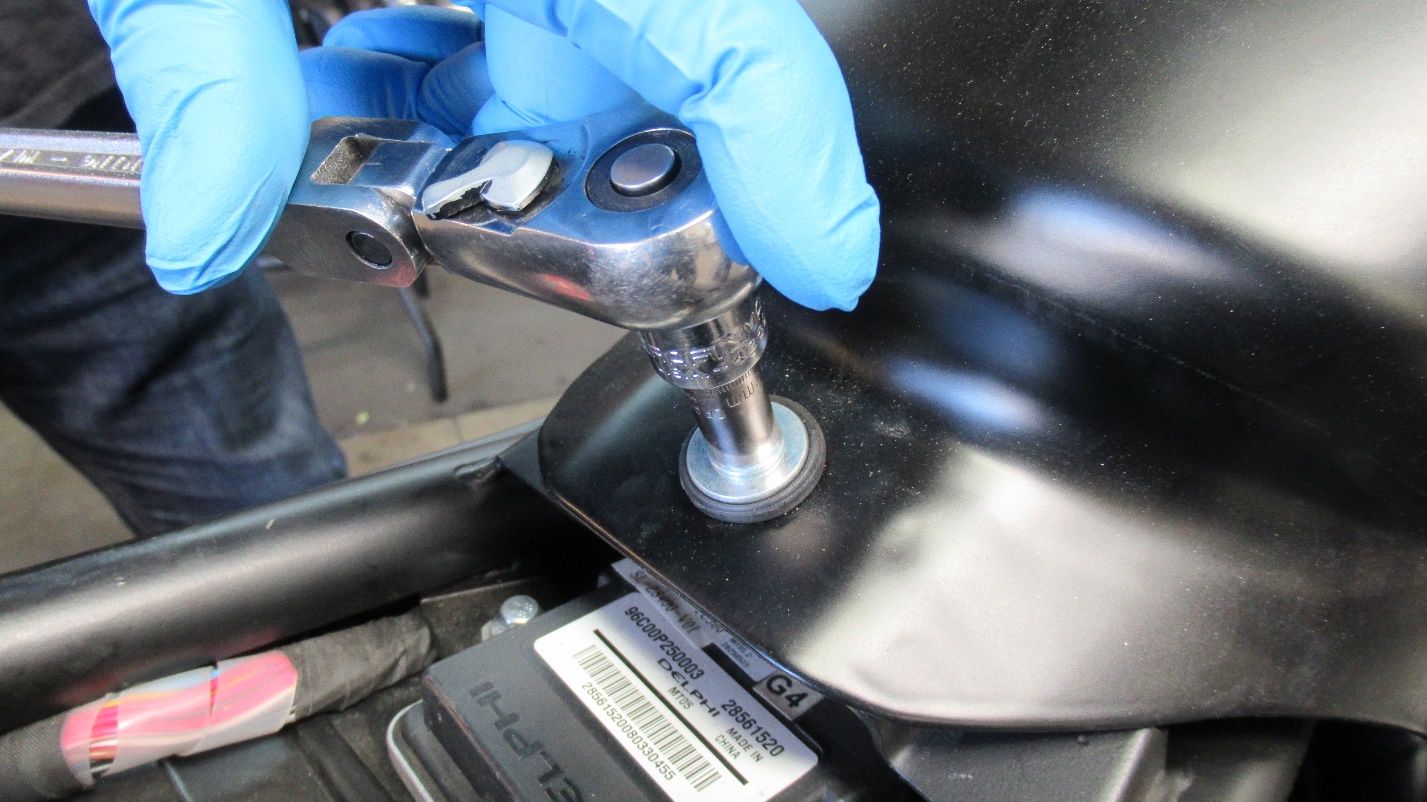
Remove the 8mm screw from the rear of the fuel tank.
Slide the tank towards the rear of the motorcycle and gently lift it up. Disconnect the two rubber hoses from the bottom of the tank. (The large hose is the fuel overflow that hangs behind the engine. The small hose is the vent line to the charcoal cannister)
Disconnect the fuel gauge plug from the right side of the tank.
Disconnect the fuel line from the bottom of the tank by pressing in the green locking tabs. Disconnect the fuel pump plug by gently lifting the black tab.
The tank can be removed from the motorcycle.
To provide access to the valve cover disconnect the spark plug wires from the spark plugs.
Remove the coil packs with coil wires from the motorcycle removing the 8mm screw.
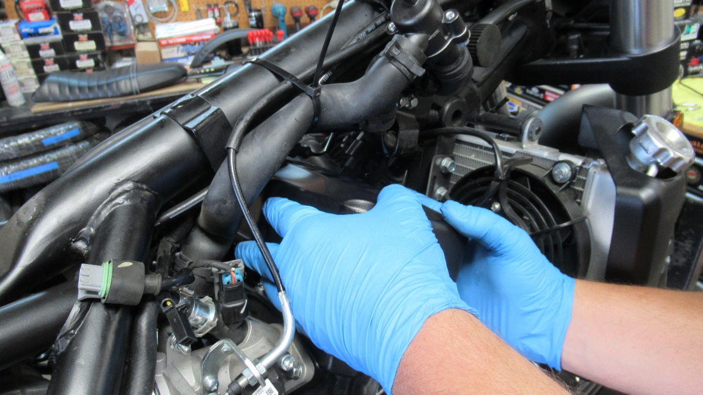
More space above the valve cover can be made by shifting the thermostat housing and coolant hoses out of the way. Remove the 8mm screw that holds the thermostat to its bracket. Pull the entire assembly and hoses towards the backbone of the frame and hold in place using zip ties.
Clean and dirt/dust on the top of the valve cover with a rag. This will prevent contaminants from entering the top of the exposed engine.
Use a 6mm allen to remove the four screws on the valve cover.
Lift the valve cover straight up and gently slide it out towards the right side.
Note the direction of the “arrow” stamping on the valve cover points forward.
Use a 13mm deep socket to remove both spark plugs.
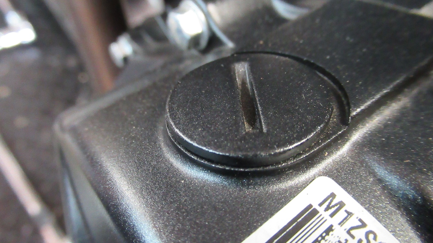
Remove the engine view port cover with a wide flathead screwdriver from the top left of the engine crankcase.
Remove the access port on the left side of the engine crankcase with a wide flathead screwdriver.
At this point, make sure the motorcycle is in neutral and bring the left side of the engine to top dead center. The way to do this is to insert a 14mm socket in the engine drive port and rotate the engine counterclockwise as viewed from the left side of the engine.
Observe the intake valve rocker on top left of the engine as you do so (it is the rocker at the rear of the cylinder head).
As soon as the left intake valve rocker actuates and then releases the intake valve, observe the engine view port at the top left the engine case (you may need a flashlight to see inside the viewport). Continue to rotate the engine slowly a few more degrees. A scribe line will come into view with a “L” oriented horizontally below the scribe line. When the scribe line is aligned with the marker in the viewport, the left side of the engine is at top dead center.
As you do this, the engine will rotate a few degrees on its own as you rotate the crankshaft with the 14mm socket. It will feel as if it is going past the compression point, but the engine is not experiencing compression because the spark plug has been removed. This self-induced engine rotation is caused by the valve springs and rockers acting on the camshaft. You can rotate the engine clockwise or counterclockwise, as necessary, to bring the scribe line into alignment with the marker as shown above.
When the left side of the engine is at top dead center as outlined above, adjust the valve gap to 0.06mm for the intake valves, and 0.08mm for the exhaust valves.
This is done by:
Loosening the locknut on the valve adjustor.
Backing the adjustor out with a screwdriver.
Inserting the feeler gage between the bottom of the adjuster and the top of the valve stem.
Moving the adjustor in with the screwdriver to contact with the feeler gage shim.
Tightening the locknut.
Take care when adjusting the threaded adjustor to not drive the valve open by screwing the adjustor in too far.
The valve adjustment is shown in the photo below. The screwdriver used to the turn the adjustor. The 8mm wrench is used to turn the locknut.
Note that the valve gaps recommended here are slightly larger than recommended by Zongshen (Zongshen recommends 0.04mm for the intake gap and 0.06mm for the exhaust gap). We have found the motorcycle runs better with the gaps set at 0.06mm for the intake gap and 0.08mm for the exhaust gap.
After completing the adjustment for the intake and exhaust valves on the left side of the engine, use the 14mm socket to rotate the engine through two complete engine revolutions and check the gaps again to make sure the adjustments are correct.
Now the adjustments will be completed on the right side of the engine.
At this point, make sure the motorcycle is in neutral and bring the right side of the engine to top dead center. The way to do this is to insert a 14mm socket in the engine drive port and rotate the engine counterclockwise as viewed from the left side of the engine.
As soon as the right intake valve rocker actuates and then releases the intake valve, observe the engine view port at the top left the engine case (you may need a flashlight to see inside the viewport). Continue to rotate the engine slowly a few more degrees. A scribe line will come into view with a “R” oriented horizontally below the scribe line. When the scribe line is aligned with the marker in the viewport, the left side of the engine is at top dead center.
As you do this, the engine will rotate a few degrees on its own as you rotate the crankshaft with the 14mm socket. It will feel as if it is going past the compression point, but the engine is not experiencing compression because the spark plug has been removed. This self-induced engine rotation is caused by the valve springs and rockers acting on the camshaft. You can rotate the engine clockwise or counterclockwise, as necessary, to bring the scribe line into alignment with the marker as shown above.
When the right side of the engine is at top dead center as outlined above, adjust the valve gap to 0.06mm for the intake valves, and 0.08mm for the exhaust valves.
After completing the adjustment, use the 14mm socket to rotate the engine through two complete engine revolutions and check the gaps again to make sure the adjustments are correct.
After adjusting the valves, reassemble the motorcycle (assembly is the reverse of disassembly).
The valve cover gasket may require replacement or preparation during the reassemble.
Using a very small amount of rubber cement or glue on the cover side of the gasket allows the gasket to be placed on the valve cover.
Silicone should be applied to the “round” ends on the engine side of the gasket.
Components and Parts
No parts are required for making the valve adjustment unless the gasket is being replaced. As outlined above, several tools and feeler gages are necessary. CSC Motorcycles stocks tool kits and feeler gages. Please call us at
for any needs.
RE3 SG400 Valve Adjustment